Book Appointment Now


Flat Swing Clamp QDK High Precision Manufacturing Solution
Description
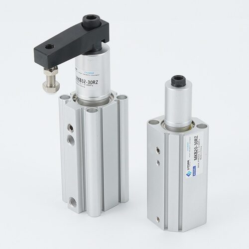
QDK Series: Horizontal Rotary Clamp Cylinder
High-Stability Precision Clamping with Zero Rotation Stroke
The QDK Series is a high-performance horizontal rotary clamp cylinder designed for advanced automation and industrial fixtures. Unlike traditional rotary cylinders, this series features a horizontal rotary construction where the complete rotation occurs on a horizontal plane, ensuring that the rotation stroke is zero and significantly saving vertical space.
——————————————————————————–
Key Technical Advantages
- Enhanced Stability: Engineered with double pins in the rotation guide groove to minimize vibration and increase operational stability during high-frequency cycles.
- Space-Saving Design: Its horizontal rotation path allows for a more compact footprint compared to vertical-swing series, making it ideal for low-clearance environments.
- Flexible Mounting: Available in two distinct front-end cap configurations—Boss type and Flush type—to accommodate various installation requirements.
- Integrated Sensing: The cylinder body is equipped with magnetic switch slots on multiple sides for the easy installation of induction sensors.
- Customizable Rotation: Supports both Levorotatory (QDKL)—anticlockwise swivel—and Dextrorotatory (QDKR)—clockwise swivel—directions with a standard rotation angle of 90°.
——————————————————————————–
Technical Specifications
| Feature | Specification Details | Source |
|---|---|---|
| Bore Sizes (mm) | 20, 25, 32, 40 | |
| Acting Type | Double Acting | |
| Fluid | Filtered Air (40μm filter element required) | |
| Operating Pressure | 0.15 | |
| Proof Pressure | 1.5MPa (220psi) | |
| Temperature Range | -20°C to 70°C | |
| Rotation Angle | 90° (Tolerance: ±3°) | |
| Repeatability | ±2° | |
| Clamping Stroke | 5 mm | |
| Cushion Type | Bumper | |
| Port Size | M5×0.8 (ø20-ø32); 1/8″ (ø40) |
——————————————————————————–
Cylinder Thrust (Force Data)
The following table provides the theoretical thrust (N) in the Clamping (Inward) direction based on operating pressure:
| Bore Size | Rod Size | 0.2 MPa | 0.4 MPa | 0.6 MPa | 0.8 MPa |
|---|---|---|---|---|---|
| 20 mm | 12 mm | 20.1 N | 60.3 N | 100.5 N | 140.7 N |
| 25 mm | 12 mm | 55.5 N | 131.1 N | 206.7 N | 282.3 N |
| 32 mm | 12 mm | 111.2 N | 250.4 N | 388.6 N | 526.8 N |
| 40 mm | 16 mm | 180.7 N | 391.7 N | 602.7 N | 813.7 N |
| (Note: Complete force data available for pressures ranging from 0.1 to 0.8 MPa). |
——————————————————————————–
Premium Material Composition
Built for durability, the major components are constructed from high-grade industrial materials:
- Cylinder Body: High-strength Aluminum Alloy.
- Piston Rod: Scr440 Steel for high tensile strength.
- Rotary Axis: Scr440 Steel.
- Seals & O-rings: NBR (Nitrile Butadiene Rubber).
- Bumper: TPU (Thermoplastic Polyurethane).
- Magnet: Sintered metal (Neodymium-iron-boron).
——————————————————————————–
Selection & Application Guidelines
- Arm Length and Pressure: When designing custom clamp arms, ensure the length and operating pressure remain within the allowable bending moment graph to prevent damage to the piston rod.
- Inertia Management: If long or heavy arms are utilized, the cylinder speed must be reduced according to the Moment of Inertia chart to protect internal components.
- Speed Control: To maximize the lifespan of the cylinder and the jig, it is mandatory to use flow control valves to regulate the swivel and clamping speed.
- Air Quality: Clean air is essential; ensure a 40μm filter is used and the piping is purged of debris before connection.
- Assembly Safety: When installing or removing a rocker arm, always secure the arm with a spanner while using an Allen wrench to tighten the bolt; never hold the cylinder body during this process to avoid internal damage
Related products
-

Swing Clamp Cylinder QCK High Precision Global Mfg Supply
-
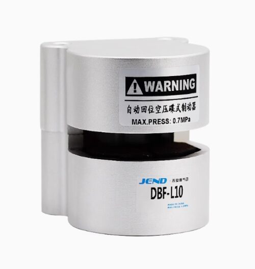

Pneumatic Caliper Brake DBF: Safety Manufacturing Solutions for the Global Industry
-
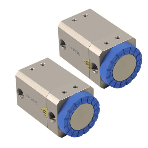

Magnetic Gripper SGM High Precision Manufacturing Solution
-
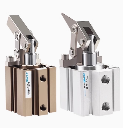

Lever Clamp Cylinder Various Series – Providing Clamping Solutions for the Global Manufacturing Industry