Book Appointment Now


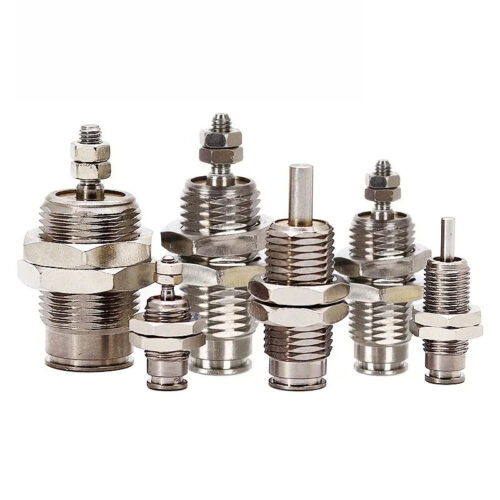
Compact Cylinders CQ2B High Precision Global Mfg Solution
Description
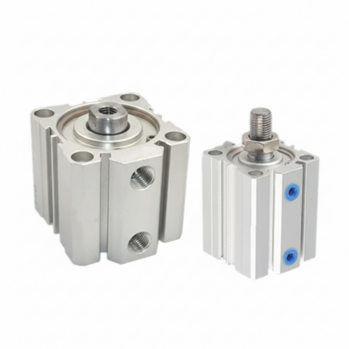
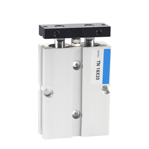
CQM Series: Compact Cylinder with Integrated Guide Rods
High-Rigidity Guided Motion with CQ2-Compatible Mounting Footprint
The CQM Series is a high-performance guided compact cylinder engineered for automation environments requiring superior non-rotating accuracy and resistance to lateral loads. By integrating guide rods directly into the cylinder body, this series eliminates the need for external guides, offering a 2 to 4 times higher resistance to lateral loads compared to standard compact cylinders.
This series is designed with mounting dimensions compatible with standard CQS and CQ2 series, allowing for seamless upgrades to existing systems where enhanced stability is required.
——————————————————————————–
Key Technical Advantages
- Integrated Guide System: Features a built-in plate and guide rods that allow loads to be mounted directly to the cylinder.
- Precision Non-Rotating Accuracy: Designed to maintain tight tolerances even at the retracted end:
- ø12, ø16: ±0.2° or less.
- ø20 to ø50: ±0.1° or less.
- Space-Efficient Sensing: Auto switches can be mounted or removed even when the plate is in the fully retracted position.
- Standardized Mounting: The through-hole mounting style (CQMB) is standard, with “both ends tapped” options available for larger bore sizes.
——————————————————————————–
Technical Specifications
| Feature | Specification Details | Source |
|---|---|---|
| Bore Sizes (mm) | 12, 16, 20, 25, 32, 40, 50 | |
| Action | Double acting, single rod | |
| Fluid | Compressed Air (Pneumatic non-lube type) | |
| Proof Pressure | 1.5 MPa | |
| Max. Operating Pressure | 1.0 MPa | |
| Min. Operating Pressure | ø12, 16: 0.12 MPa / ø20–50: 0.1 MPa | |
| Ambient & Fluid Temp. | -10°C to 70°C (No switch) / -10°C to 60°C (With switch) | |
| Cushion | Rubber bumper at both ends | |
| Piston Speed | 50 to 500 mm/s (ø12–40) / 50 to 300 mm/s (ø50) | |
| Stroke Tolerance | +1.0 mm / 0 |
——————————————————————————–
Theoretical Output Force (Unit: N)
Data based on 0.5 MPa operating pressure.
| Bore Size (mm) | Operating Direction | Output Force (0.5 MPa) |
|---|---|---|
| 12 | OUT / IN | 57 N / 42 N |
| 20 | OUT / IN | 157 N / 118 N |
| 32 | OUT / IN | 402 N / 302 N |
| 50 | OUT / IN | 982 N / 825 N |
——————————————————————————–
Standard Stroke Availability
Available in 1 mm increments via spacers installed in standard stroke bodies,.
| Bore Size (mm) | Standard Stroke Range (mm) | Source |
|---|---|---|
| 12, 16 | 5, 10, 15, 20, 25, 30 | |
| 20, 25 | 5, 10, 15, 20, 25, 30, 35, 40, 45, 50 | |
| 32, 40, 50 | 5*, 10, 15, 20, 25, 30, 35, 40, 45, 50, 75, 100 | |
| *ø50 starts from 10mm standard stroke. |
——————————————————————————–
Materials and Construction
| Component | Material | Treatment / Notes | Source |
|---|---|---|---|
| Cylinder Tube | Aluminum Alloy | Hard Anodized | , |
| Plate | Aluminum Alloy | ø12–40: Anodized; ø50: Chromated/Coated | , |
| Guide Rod | Stainless Steel / Carbon Steel | ø32–50: Hard Chrome Plated | , |
| Piston Rod | Stainless Steel / Carbon Steel | ø32–50: Hard Chrome Plated | , |
| Bushing | Sintered Alloy / Bronze Casting | Oil-impregnated for smooth motion | |
| Seals | NBR | Rod and Piston Seals | , |
——————————————————————————–
Engineering Precautions
- Stopper Use: This product is designed for guided motion and should not be used as a stopper.
- Kinetic Energy: Users must ensure operation stays within the allowable kinetic energy and rotational torque ranges to prevent damage,.
- Lateral Load: Strictly adhere to the allowable lateral load ranges to ensure the rated service life of the guide rods