Book Appointment Now


Compact Slide Table HLQ High Precision Industry Solution
Description
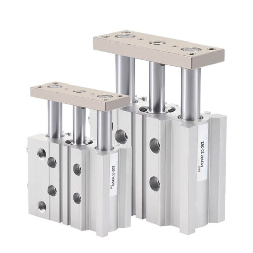
HLQ Series: High-Precision Dual-Rod Slide Table Cylinder
Precision Linear Motion with Recirculating Ball Bearing Technology
The HLQ Series is a high-rigidity slide table cylinder engineered for automation applications requiring exceptional precision, stability, and load-bearing capacity. Utilizing a recirculating ball bearing guide system and a dual-rod construction, this series ensures smooth, accurate linear motion and superior resistance to moments.
——————————————————————————–
Technical Performance Standards
The HLQ series offers high kinetic energy absorption and robust load handling. Performance varies by bore size and the type of cushioning used.
1. Kinetic Energy and Load Capacity
| Model | Basic Type Max. Emax (J) | Adjustable Bolt Max. Emax (J) | Hydraulic Shock Absorber Max. Emax (J) | Max. Allowable Load Wmax (N) |
|---|---|---|---|---|
| HLQ6 | 0.01 | 0.01 | — | 4 |
| HLQ8 | 0.024 | 0.024 | 0.048 | 8 |
| HLQ12 | 0.05 | 0.05 | 0.1 | 15 |
| HLQ16 | 0.1 | 0.1 | 0.2 | 30 |
| HLQ20 | 0.13 | 0.13 | 0.26 | 40 |
| HLQ25 | 0.22 | 0.22 | 0.44 | 70 |
2. Allowable Torque Capacity
The series is designed to handle static and dynamic moments (Pitch, Yaw, and Roll) efficiently.
- Pitching Moment (Mp): High resistance to forward/backward tilting loads.
- Yawing Moment (My): High stability against side-to-side rotation.
- Rolling Moment (Mr): Robust performance under axial rotational loads.
——————————————————————————–
Engineering & Installation Data
Cylinder Mounting Torque Specifications
To maintain accuracy and prevent mechanical failure, please adhere to the following locking torque ranges:
| Model | Bolt Thread | Max. Locking Torque (Nm) | Max. Depth (mm) |
|---|---|---|---|
| HLQ6 | M4 × 0.7 / M3 × 0.5 | 2.1 / 1.2 | 8.0 |
| HLQ8 | M4 × 0.7 / M3 × 0.5 | 2.1 / 1.2 | 9.6 |
| HLQ12 | M5 × 0.8 / M4 × 0.7 | 4.4 / 2.8 | 13.4 |
| HLQ16 | M6 × 1.0 / M5 × 0.8 | 4.4 / 5.7 | 16.7 |
| HLQ20 | M6 × 1.0 / M5 × 0.8 | 7.4 / 5.7 | 22.0 |
| HLQ25 | M8 × 1.25 / M6 × 1.0 | 18.0 / 10.0 | 27.0 |
Fixture Mounting Torque
When installing fixtures to the front or top plate, ensure bolts do not exceed the specified depth to avoid interference with the guide rail:
- Example (HLQ12): Max Torque 4.4 Nm; Max Depth 8.0 mm (Front) / 5.0 mm (Top).
——————————————————————————–
Key Features for Integration
- Symmetrical Design (HLQL): Available in both standard (HLQ) and symmetrical (HLQL) configurations to optimize space and piping in mirrored machine layouts.
- Hydraulic Shock Absorbers: Compatible with the ACA series for increased energy absorption (e.g., HLQ12 uses ACA0806-1N).
- Integrated Sensing: Prepared for CMSH or DMSH series magnetic sensors. When installing sensors on adjacent cylinders, maintain at least a 3mm gap to prevent interference.
- Precision Displacement Control: Engineered for minimal displacement under load. For example, at a 100mm stroke, the HLQ25 maintains high stability under varying rolling and pitching moments.
——————————————————————————–
Operational Guidelines
- Speed Limit: Ensure the operating speed remains under 500 mm/s to prevent excessive wear and maintain precision.
- Lubrication: Use turbine oil (ISO VG32) if lubrication is required; once initiated, lubrication must be maintained.
- Shock Absorber Maintenance: The shock absorber is a consumable part. Replace promptly if energy absorption capacity declines. Do not rotate the bottom screw of the shock absorber to avoid oil leakage.
- Load Management: Actual loads and moments must be calculated based on the center of gravity and stroke to ensure they fall within the permissible ranges defined in the technical charts