Book Appointment Now


Magnetically Coupled Rodless Cylinder RMT – Providing Advanced Manufacturing Solutions for the Global Industry
Description
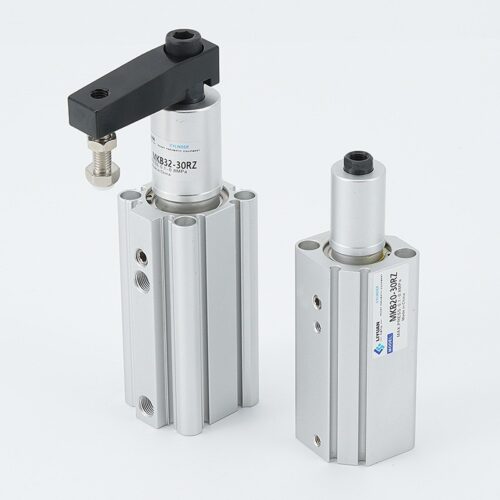
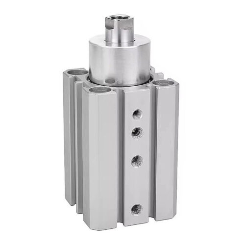
RMT Series: Guided Rodless Cylinder (Magnetically Coupled)
High-Precision Linear Motion with Integrated Dual Guides
The RMT Series is a high-performance, magnetically coupled pneumatic rodless cylinder designed for applications where space efficiency and high-load precision are critical. By utilizing a mobile internal piston fitted with annular magnets to drive an external carriage, this series provides a completely leak-proof and compact design. The integrated dual guides ensure superior linearity and high resistance to side or offset loads.
——————————————————————————–
Technical Specifications
| Feature | Specification Details | Source |
|---|---|---|
| Bore Sizes (mm) | 16, 20, 25, 32, 40 | |
| Action Type | Double Acting | |
| Fluid | Air (filtered by 40μm filter element) | |
| Operating Pressure | ø16: 0.2 | |
| Proof Pressure | 1.2 MPa (175 psi) | |
| Ambient & Fluid Temp. | -20°C to 70°C | |
| Speed Range | 50 to 400 mm/s | |
| Stroke Tolerance | 0 | |
| Port Size | M5×0.8 (ø16); 1/8″ (ø20/25/32); 1/4″ (ø40) |
——————————————————————————–
Performance and Holding Force
The magnetic coupling determines the safe holding force required to maintain the connection between the piston and the carriage during movement.
| Bore Size (mm) | Safe Holding Force (N) | Max. Load W (kg) | Max. Standard Stroke (mm) | Source |
|---|---|---|---|---|
| 16 | 140 | 5.6 | 750 | , |
| 20 | 220 | 9.6 | 1000 | , |
| 25 | 345 | 16.0 | 1500 | , |
| 32 | 560 | 24.0 | 1500 | , |
| 40 | 880 | 40.0 | 1500 | , |
——————————————————————————–
Key Engineering Features
- Integrated Cushioning System: Standard models include non-adjustable rubber bumpers and adjustable pneumatic cushioning at both ends for smooth deceleration. For high-impact applications, optional shock absorbers (ACA series) are available to provide perfect cushioning.
- Dust-Proof Construction: The physical isolation between the carriage and the internal piston ensures the mechanism remains protected from environmental contaminants.
- High Load Rigidity: The dual-guide design is specifically engineered to handle offset loads. For optimal performance, the loading center and the slide table center must be superposed.
- Sensor Integration: The cylinder body includes integrated mounting holes for sensor switch rails, compatible with CMSG, DMSG, and EMSG series switches for position detection.
——————————————————————————–
Component Materials
(Based on Internal Structure)
| No. | Component | Material | Source |
|---|---|---|---|
| 3 | Cylinder Barrel | Stainless Steel | |
| 6, 19 | Magnets | Rare-earth permanent magnets | |
| 9 | Wear Ring | Special wear-resistant resin | |
| 11, 31 | Bumpers | High-durability elastomer | |
| 30 | Guides | Precision-ground steel rails |
——————————————————————————–
Installation & Maintenance Guidelines
- Workpiece Selection: To ensure maximum operational life, it is recommended to use non-magnetically conductive materials for workpieces. Using magnetically conductive materials may halve the product’s lifespan.
- Load-Velocity Management: Engineers should consult the horizontal and vertical load-velocity charts to select the appropriate bore size based on required load (W) and moving velocity (V).
- Shock Absorber Maintenance: Shock absorbers are considered consumable parts. They must be replaced when a decrease in energy absorption capacity is noticed. Use specific tightening torques (e.g., 3.14 Nm for ø25; 10.80 Nm for ø40) during installation.
- Thread Standards: Standard ports are Metric for ø16; NPT and G threads are available for North American and European standard compliance