Book Appointment Now


Linear Guide Slide Table HLH High Precision Global Industry
Description
HLH Series: Side-Rail Precision Slide Table Cylinder
The HLH Series is a high-performance precision slide table cylinder featuring an integrated micro-circulating ball rail system. Designed for space-constrained and high-accuracy assembly environments, this series offers superior linearity and non-rotating accuracy. Its integrated structure combines the cylinder and guide rail into a single unit to minimize mounting footprints and optimize performance.
——————————————————————————–
Key Technical Features
- Integrated Design: Features a micro ball-bearing linear guide rail integrated with the cylinder body for enhanced precision and rigidity.
- Multi-Directional Mounting: The cylinder can be mounted from four distinct directions (side, bottom, and ends) to suit various mechanical layouts.
- Flexible Porting: Three sets of intake and exhaust ports are available (end, side, and bottom) to allow for versatile piping configurations.
- High Precision: Excellent linearity and non-rotating accuracy make it ideal for precision assembly and picking tasks.
- Position Sensing: Integrated sensor slots on both sides support CMSH, DMSH, and EMSH auto switches.
——————————————————————————–
Technical Specifications
The HLH series is designed for double-acting operation using filtered compressed air.
| Feature | Specification Details | Source |
|---|---|---|
| Bore Sizes (mm) | 6, 10, 16, 20 | |
| Action Type | Double Acting | |
| Operating Fluid | Air (filtered through a 40μm element) | |
| Operating Pressure | ø6: 0.2–0.7 MPa (29–100 psi) <br> ø10–20: 0.15–0.7 MPa (22–100 psi) | |
| Proof Pressure | 1.2 MPa (175 psi) | |
| Ambient & Fluid Temp. | -20°C to 70°C | |
| Speed Range | 50 to 500 mm/s | |
| Stroke Tolerance | 0+1.0 mm | |
| Cushion Type | Bumper at both ends | |
| Port Size | M5 × 0.8 |
——————————————————————————–
Theoretical Output Force (Unit: N)
Output forces are calculated based on operating pressure (MPa) for both Extension (Out) and Retraction (In).
| Bore (mm) | Direction | 0.2 MPa | 0.3 MPa | 0.4 MPa | 0.5 MPa | 0.6 MPa | 0.7 MPa |
|---|---|---|---|---|---|---|---|
| 6 | Out / In | 5.7 / 4.2 | 8.5 / 6.4 | 11.3 / 8.5 | 14.2 / 10.6 | 17.0 / 12.7 | 19.8 / 14.8 |
| 10 | Out / In | 15.7 / 13.2 | 23.6 / 19.8 | 31.4 / 26.4 | 39.3 / 33.0 | 47.1 / 39.6 | 55.0 / 46.2 |
| 16 | Out / In | 40.2 / 34.5 | 60.3 / 51.8 | 80.4 / 69.1 | 100.5 / 86.4 | 120.6 / 103.6 | 140.7 / 120.9 |
| 20 | Out / In | 62.8 / 52.8 | 94.2 / 79.1 | 125.6 / 105.5 | 157.0 / 131.9 | 188.4 / 158.3 | 219.8 / 184.7 |
——————————————————————————–
Dynamic and Static Load Capacity
1. Allowable Static Torque (Nm)
These values represent the maximum allowable torque for Pitch (Mp), Yaw (My), and Roll (Mr).
| Model | Pitching Mp | Yawing My | Rolling Mr |
|---|---|---|---|
| HLH6 | 0.25 | 0.25 | 0.41 |
| HLH10 | 0.95 | 0.95 | 1.49 |
| HLH16 | 3.28 | 3.28 | 3.45 |
| HLH20 | 6.29 | 6.29 | 6.61 |
2. Max. Allowable Kinetic Energy (J)
- HLH6: 0.008 J
- HLH10: 0.025 J
- HLH16: 0.05 J
- HLH20: 0.1 J
——————————————————————————–
Construction Materials
| Component | Material | Source |
|---|---|---|
| Slide Table | Aluminum Alloy | |
| Piston Rod | Stainless Steel | |
| Body | Aluminum Alloy | |
| Guide Rail | Stainless Steel | |
| Seals (O-Rings) | NBR | |
| Vanish/Bumper | TPU |
——————————————————————————–
Installation and Maintenance Guidelines
- Air Quality: Ensure the piping is cleared of debris before connection. Use air filtered by a 40μm element or finer.
- Environmental Protection: In low-temperature environments, take anti-freezing measures. If the unit is not used for long periods, apply anti-rust treatment to the piston rod and exposed surfaces.
- Torque Control: When mounting the cylinder or workpieces, strictly adhere to the maximum tightening torque specifications (e.g., 2.5 Nm for M4 bolts on HLH10) to avoid damaging the body or guide rail.
- Selection: Actual load and moment must fall within the allowable curves provided in the technical selection guide, considering maximum speed and eccentric distance.
- Force Alignment: The output force should be centered on the piston rod axis. Avoid eccentric loads that could cause misalignment or damage
Related products
-
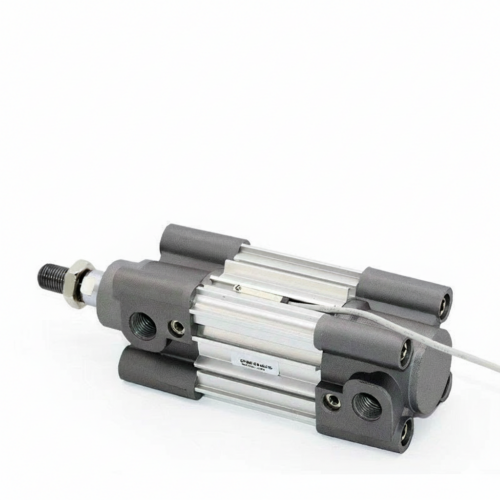

Profile Cylinder CP96 Providing high-precision manufacturing solutions for the global industry
-
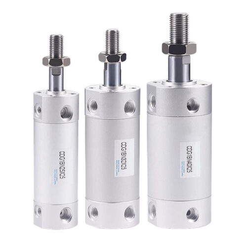

Round Body Cylinder CDG1BN High Precision Global Solution
-
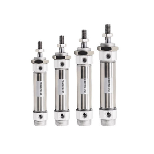

Round Body Cylinder (Metric) CDM2B: High-Precision Metric Solutions for Global Manufacturing
-
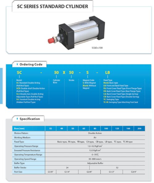

Tie-rod Cylinders SC High Precision Global Industry Mfg