Book Appointment Now

Magnetically Coupled Rodless Cylinder CY3B – Providing Seamless Solutions for the Global Industry
Description
Technical Product Specification: CY3B Series Magnetically Coupled Rodless Cylinder
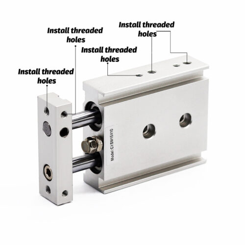
The CY3B Series is a high-performance, basic-type magnetically coupled rodless cylinder designed for space-saving automation. It features an improved design that enhances durability, reduces sliding resistance, and minimizes overall weight for modern industrial applications.
——————————————————————————–
1. Key Engineering Features
- Enhanced Durability: The wear ring length is increased by 70%, significantly improving bearing performance compared to earlier models.
- Integrated Lubrication: A special resin lubretainer is installed on the dust seal to maintain ideal lubrication on the external surface of the cylinder tube.
- Low-Pressure Operation: Due to the lubretainer, the minimum operating pressure is reduced by 30%.
- Lightweight Construction: Body weight has been reduced by approximately 10% (specifically for ø50 and ø63 models) by optimizing the cylinder tube’s outer diameter.
- Non-Contact Design: The magnetically coupled design eliminates the need for mechanical connections through the cylinder wall, ensuring a leak-free environment.
——————————————————————————–
2. Technical Specifications
| Feature | Specification Details | Source |
|---|---|---|
| Bore Sizes (mm) | ø6, ø10, ø15, ø20, ø25, ø32, ø40, ø50, ø63 | |
| Fluid | Compressed Air | |
| Action | Double Acting | |
| Proof Pressure | 1.05 MPa | |
| Max. Operating Pressure | 0.7 MPa | |
| Min. Operating Pressure | 0.12 to 0.16 MPa (varies by bore size) | |
| Ambient & Fluid Temp. | –10 to 60°C (No freezing) | |
| Piston Speed | 50 to 500 mm/s | |
| Cushion Type | Rubber Bumper | |
| Lubrication | Non-lube (Factory pre-lubricated) | |
| Stroke Tolerance | 0–250st: +1.0mm; 251–1000st: +1.4mm; 1001st+: +1.8mm | |
| Mounting Orientation | Horizontal, Inclined, Vertical |
——————————————————————————–
3. Magnet Holding Force and Stroke Capacity
The magnetic coupling determines the allowable load and driving force. Operating beyond these limits may result in the magnetic coupling breaking or slipping.
| Bore Size (mm) | Magnet Holding Force (N) | Max. Available Stroke (mm) | Port Size (Rc/NPT/G) |
|---|---|---|---|
| ø6 | 19.6 | 300 | M3 x 0.5 |
| ø10 | 53.9 | 500 | M5 x 0.8 |
| ø15 | 137 | 1000 | M5 x 0.8 |
| ø20 | 231 | 1500 | 1/8″ |
| ø25 | 363 | 3000 | 1/8″ |
| ø32 | 588 | 5000 | 1/8″ |
| ø40 | 922 | 5000 | 1/4″ |
| ø50 | 1471 | 3000 | 1/4″ |
| ø63 | 2256 | 3000 | 1/4″ |
(Note: Intermediate strokes are available in 1 mm intervals.)
——————————————————————————–
4. Material Composition
| Component | Material | Notes | Source |
|---|---|---|---|
| Body / Head Cover | Aluminum Alloy | Hard Anodized | |
| Cylinder Tube | Stainless Steel | High Precision | |
| Piston / Shaft | Stainless Steel / Rolled Steel | ||
| Magnets | Rare Earth / Sintered | High holding force | |
| Seals / Gaskets | NBR | ||
| Wear Ring | Special Resin | ||
| Bumper | Urethane Rubber |
——————————————————————————–
5. Design and Application Precautions
- External Guiding: The CY3B series does not have an integrated guide. It must be guided by an external axis, such as a linear guide, to prevent lateral loads and rotation of the external slider.
- Deflection Management: Longer strokes increase the deflection of the cylinder tube due to its own weight. Mounting brackets and clearances (typically 0.2 to 0.5 mm) must be calculated to assimilate this deflection.
- Vertical Operation: When operating vertically, ensure the load does not exceed the allowable vertical mass (e.g., 18.5 kg for ø25) to prevent the magnetic coupling from breaking and dropping the load.
- Intermediate Stops: If stopping mid-stroke via an external stopper, operating pressure must remain within specified limits (e.g., 0.65 MPa for ø15–ø63) to avoid decoupling. Intermediate stops using pneumatic circuits are not permitted in vertical orientations.
- Magnetic Caution: The attractive power of the internal and external magnets is extremely strong. Exercise caution during disassembly to prevent injury or damage to the magnetic components