Book Appointment Now


Magnetically Coupled Rodless Cylinder CY3R: High-Precision Manufacturing Solutions for Global Markets
Description
Series CY3R: Direct Mount Magnetically Coupled Rodless Cylinder
High-Precision, Space-Saving Linear Actuation
The Series CY3R is a direct-mount, magnetically coupled rodless cylinder designed for modern automation where space efficiency and mounting rigidity are paramount. This upgraded version features significant enhancements in durability and performance, including a 70% longer wear ring for improved bearing life and an integrated resin lubretainer on the dust seal to ensure consistent lubrication of the cylinder tube.
——————————————————————————–
Technical Specifications
The CY3R series is engineered to operate reliably under standard industrial pneumatic conditions.
| Feature | Specification Details | Source |
|---|---|---|
| Bore Sizes (mm) | ø6, ø10, ø15, ø20, ø25, ø32, ø40, ø50, ø63 | |
| Fluid | Compressed Air | |
| Action | Double Acting | |
| Proof Pressure | 1.05 MPa | |
| Max. Operating Pressure | 0.7 MPa | |
| Min. Operating Pressure | 0.12 to 0.16 MPa (varies by bore size) | |
| Ambient & Fluid Temp. | –10 to 60°C (No freezing) | |
| Piston Speed | 50 to 500 mm/s* | |
| Cushion Type | Rubber bumper | |
| Lubrication | Non-lube (Factory pre-lubricated with lubretainer) | |
| Stroke Tolerance | 0–250st: +1.0mm; 251–1000st: +1.4mm; 1001st+: +1.8mm | |
| Mounting Orientation | Horizontal, Inclined, Vertical |
*When using auto switches in intermediate positions, maintain speed at 300 mm/s or below to ensure relay operation.
——————————————————————————–
Performance & Holding Force
The magnetic coupling determines the cylinder’s holding capacity. Exceeding these limits can result in the decoupling of the internal and external sliders.
| Bore Size | Magnet Holding Force (N) | Max. Stroke without Switch (mm) | Max. Stroke with Switch (mm) | Source |
|---|---|---|---|---|
| ø6 | 19.6 | 300 | 300 | |
| ø10 | 53.9 | 500 | 500 | |
| ø15 | 137 | 1000 | 750 | |
| ø20 | 231 | 1500 | 1000 | |
| ø25 | 363 | 2000 | 1200 | |
| ø32 | 588 | 2000 | 1500 | |
| ø40 | 922 | 2000 | 1500 | |
| ø50 | 1471 | 2000 | 1500 | |
| ø63 | 2256 | 2000 | 1500 |
——————————————————————————–
Direct Mounting & Accuracy
The “Direct Mount” configuration allows the cylinder body to be bolted directly to the machine frame, enhancing rigidity and simplifying alignment.
Non-rotating Accuracy & Allowable Moment
(Reference values for models with switch rails)
| Bore Size (mm) | Non-rotating Accuracy (°) | Max. Allowable Moment MD (N·m) | Source |
|---|---|---|---|
| ø15 | 4.5 | 0.15 | |
| ø25 | 3.7 | 0.25 | |
| ø40 | 2.8 | 0.62 | |
| ø63 | 2.2 | 1.37 |
Maximum Load Mass (Loaded Directly on Body)
| Model | ø6 | ø15 | ø25 | ø40 | ø63 | Source |
|---|---|---|---|---|---|---|
| WBmax (kg) | 0.2 | 1.0 | 1.2 | 2.0 | 3.0 |
——————————————————————————–
Material Construction
| Component | Material | Treatment/Notes | Source |
|---|---|---|---|
| Body / End Covers | Aluminum Alloy | Hard Anodized | |
| Cylinder Tube | Stainless Steel | High Precision | |
| Piston / Shaft | Stainless Steel / Rolled Steel | ||
| Magnets | Rare Earth / Sintered | Titanium Nitride Coating (External) | |
| Seals | NBR | ||
| Wear Rings | Special Resin | 70% length increase |
——————————————————————————–
Engineering & Safety Precautions
- Alignment: Long-stroke applications increase shaft deflection. For strokes where deflection is a concern, use a floating mechanism (e.g., XC57) to assimilate center axis variations.
- Vertical Operation: Do not exceed the allowable vertical mass (e.g., 18.5 kg for ø25) to prevent accidental load drops.
- Intermediate Stops: If using an external stopper, ensure operating pressure stays within safety limits (e.g., 0.65 MPa for ø15–63) to avoid magnetic decoupling.
- Auto Switch Integration: Small auto switches (D-M9, D-A9) can be mounted flush in the integrated grooves for all sizes ø6 to ø63.
- Magnetic Safety: The magnets have extremely strong attractive force. Handle with extreme caution during any disassembly or maintenance
Related products
-
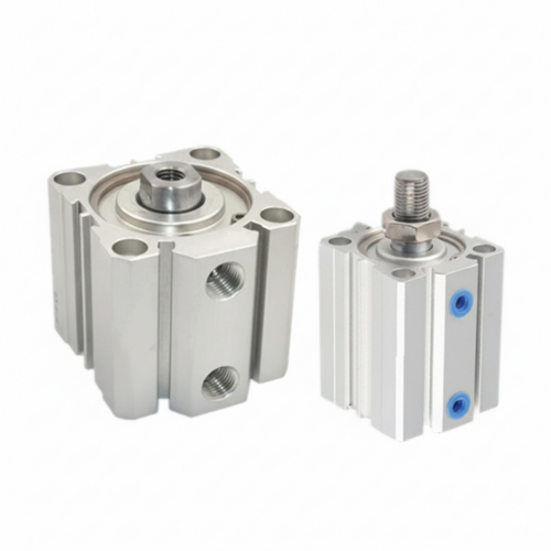

Compact Cylinders ACQ High Precision Manufacturing Solution
-
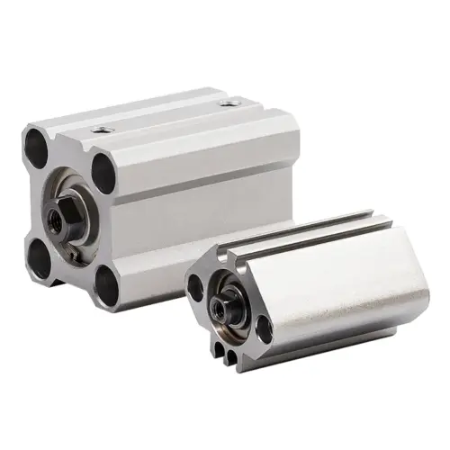

Compact Cylinders CQ2B High Precision Global Mfg Solution
-
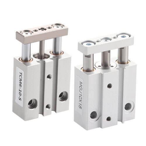

Miniature Guide Rod Cylinder MGJ/TCM: High-Precision Solutions for Global Electronics Manufacturing
-
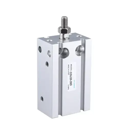

Free Mount Cylinder (with Magnet) CDU: High-Precision Magnetic Solutions for Global Manufacturing